A PID (Proportional Integral Derivative) controller works by controlling an output to bring a process value to a desired set point.
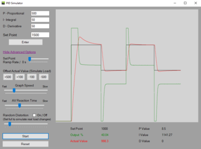
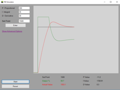
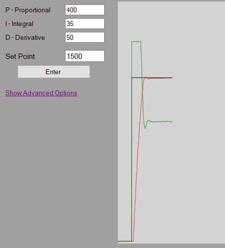
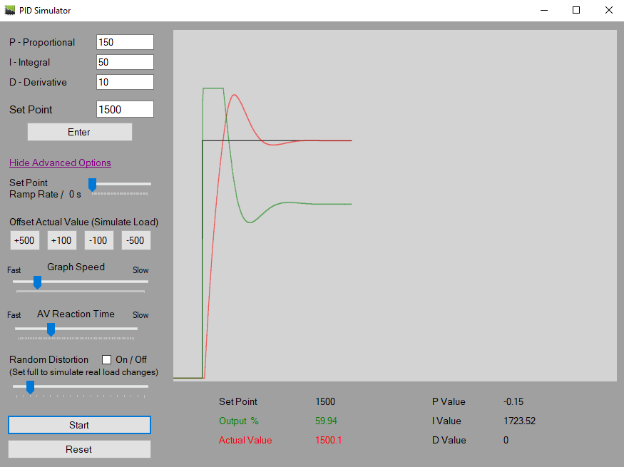
See post “WHAT IS A PID CONTROLLER?” for a basic example of a PID controller. You can also visit the PID Simulator page to try the interactive PID Simulator tool!
Before we dive into the PID controller, there is a few terms that need defined:
PID Controller Terms:
Set Point
The set point is normally a user entered value, in cruise control it would be the set speed, or for a heating system, it would be the set temperature.
Process Value
The process value is the value that is being controlled. For cruise control this would be the actual vehicle speed, or in a heating system, this would be the current temperature of the system.
Output
The output is the controlled value of a PID controller. In cruise control, the output would be the throttle valve, in a heating system, the output might be a 3 way valve in a heating loop, or the amount of fuel applied to a boiler.
Error
The error value is the value used by the PID controller to determine the how to manipulate the output to bring the process value to the set point.
Error = Setpoint – Process Value
PID Controller Explained!
At a basic level, a PID controller continuously monitors the error value. It uses that error to calculate the proportional, integral, and derivative values, then combines those values to create the controller output.
Below, we will look at proportional, integral, and derivative control as three separate parts before combining them into the final output. But first, we need to talk about the user input values in a PID controller: the gain settings, commonly called P-Gain, I-Gain, and D-Gain.
Gain
Gain is another way of describing a multiplication factor. By adjusting the proportional, integral, and derivative gain settings, the user can change how much influence each part of the PID calculation has on the output and how the controller responds to changes in the process value.
P or Proportional
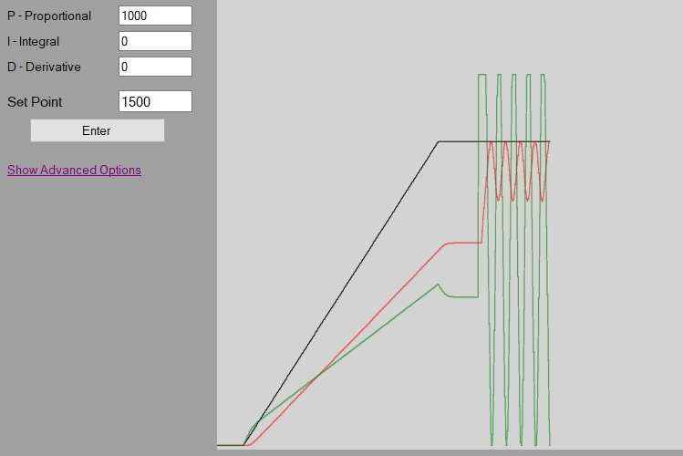
The Proportional is calculated by multiplying the P-Gain by the error. The purpose of the proportional, is to have a large immediate reaction on the output to bring the process value close to the set point. As the error becomes less, the influence of the proportional value on the output becomes less.
The Proportional math looks like this:
P = Proportional | kP = Proportional Gain | SP = Set point | PV = Process Value | Err = Error
Err = SP – PV
P = kP x Err
I or Integral
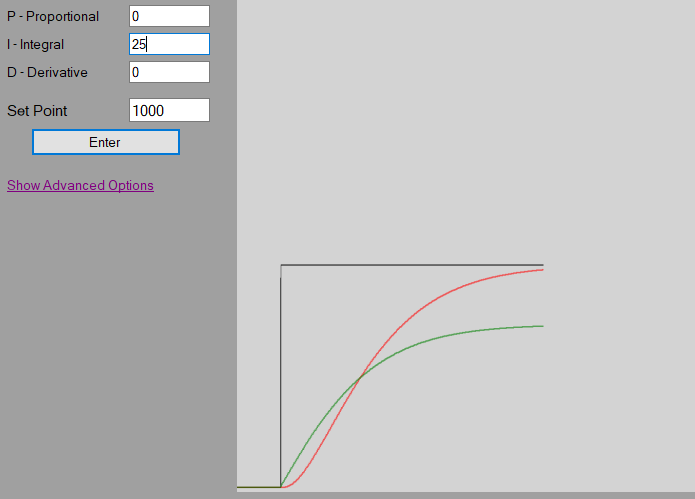
The Integral is calculated by multiplying the I-Gain, by the error, then multiplying this by the cycle time of the controller (how often the controller performs the PID calculation) and continuously accumulating this value as the “total integral”.
Explained a little further, every time the controller performs the PID calculation (example of a cycle time is every 100 ms), the new calculated integral value, is added to the integral total. The integral will normally not have as much immediate influence on the output as the proportional, but because the integral is continuously accumulating overtime, the longer it takes for the process value to reach the set point, the more effect the integral will have on the output.
And the Integral math:
I = Integral | kI = Integral Gain | dt = cycle time of the controller | It = Integral Total
I = kI x Err x dt
It = It + I
D or Derivative
The derivative is calculated by multiplying the D-Gain by the ramp rate of the process value. The purpose of the derivative is to “predict” where the process value is going, and bias the output in the opposite direction of the proportional and integral, to hopefully prevent the controller from over-shooting the set point if the ramp rate is to fast.
Explained a bit simpler, if the process value is approaching the set point to fast, the derivative will limit the output to prevent the process value from overshooting the set point.
The Derivative Math:
D = Derivative | kD = Derivative Gain | dt = cycle time of the controller | pErr = Previous Error
D = kD x (Err – pErr) / dt
Output
The PID controller output is calculated by simply adding the Proportional, the Integral and the Derivative. Depending on the gain setting of these three values, will determine how much effect they will have on the output.
PID Controller Output Math:
Output = P + It + D
All together a PID control loop looks like this;
Err = Sp – PV
P = kP x Err
It = It + (Err x kI x dt)
D = kD x (pErr – Err) / dt
pErr = Err
Output = P + It + D
Wait dt (100 ms), and perform loop again.
Tuning a PID controller
Check out this post to learn how to tune a PID controller and an example of how to set one up from scratch.
Disclaimer
By accessing, downloading, installing, viewing, or using this application, website, videos, or related content, you acknowledge and agree to the full Disclaimer found at https://pidexplained.com/disclaimer/. This application, website, videos, and related content are provided for general informational and simulation practice purposes only. All settings, values, examples, outputs, demonstrations, and scenarios are simulated examples only, may not be accurate, complete, current, or error-free, and must not be copied, transferred, relied on, or applied to any actual controller, device, equipment, system, or process. This content is not OEM training, real-world tuning guidance, commissioning guidance, field instruction, or a substitute for qualified procedures, OEM documentation, training, or applicable requirements; use of this content does not qualify any person to tune, configure, adjust, or operate any real-world controller, device, equipment, system, or process, and any such work should only be performed by a properly qualified person.