PID tuning can be difficult when trying to understand where to start and how different adjustments affect controller response. This article provides a general overview of PID tuning concepts, including common starting points, adjustment direction, and basic tuning considerations.
To start, read “PID Controller Explained“for a basic explanation of what a PID controller is and how it works. And also the PID Simulator page to try the interactive PID simulation tool.
It is helpful to note early on that there can be more than one set of values that produces an acceptable response for the same control objective. The goal is not always to find the “perfect” values, but to find values that meet the applicable requirements and provide the desired control response.
Finding Initial PID Values
Before making tuning changes, it is important to remember that poor control response is not always caused by PID values. Mechanical issues, sensor problems, actuator limitations, process conditions, or other system factors can all affect loop behaviour. These items should be reviewed using the appropriate OEM documentation, site procedures, and qualified personnel before controller adjustments are considered.
Proportional
As a simulation exercise, start with the Integral and Derivative values set to 0, then gradually increase the Proportional value while observing the simulated loop response.
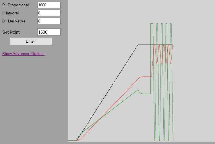
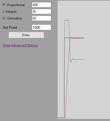
As the Proportional value increases, the simulated response may begin to oscillate. If the oscillations become smaller over time, the simulated loop is moving toward a stable response. If the oscillations continue to grow, the simulated loop is becoming unstable.
Once a Proportional value is found that causes sustained or increasing oscillation in the simulation, a common practice exercise is to reduce that value by half and use it as a starting point for further simulated tuning.
Example: if the Proportional gain that causes the simulated loop to become unstable is 1000, then a simulated starting Proportional value would be 500.
Integral
Once a simulated starting Proportional value is selected, the Integral value can be explored. In a simulation exercise, Integral adjustments should be made in small increments so the change in the simulated loop response can be observed.
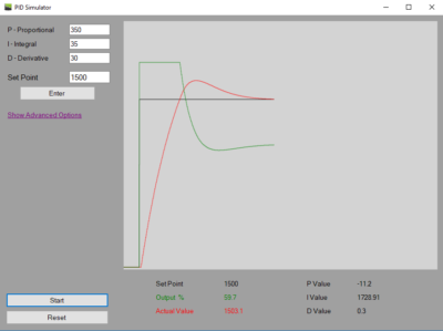
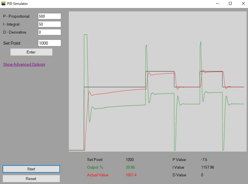
As the Integral value is increased, users can change the set point and observe how the simulated loop responds after the initial Proportional response. The purpose of this step is to see how Integral action affects the time it takes for the simulated process value to move toward the set point and reduce steady-state error.
If the simulated loop begins to oscillate or become unstable, the Integral value can be adjusted in the opposite direction to observe how the response changes. Once the simulated loop is stable and responding as desired, the example can be treated as a basic PI control simulation.
I will post a video at the bottom of this article showing these concepts inside the PID Simulator for those who prefer a visual walkthrough.
For the hands on learners, download the PID Simulator app from the Microsoft Store to explore these concepts in an interactive simulation environment.
Derivative
Many control loops can operate using PI control only, depending on the control objective. Derivative action can be used to observe how rate-of-change response affects overshoot and stability.
In a simulation exercise, once a stable PI response is achieved, the Derivative value can be increased slowly while changing the set point and observing how the simulated loop responds over time.
The purpose of the D value is to respond to how quickly the process value is changing. This can help reduce overshoot by adjusting the output based on the rate of change rather than only the current error or accumulated error.
As the Derivative value is increased in the simulation, users can observe whether overshoot is reduced to an acceptable level. If the simulated loop begins to react poorly, such as with unexpected output changes, poor control response, or oscillation, the Derivative value can be reduced to observe how stability changes.
Care should be taken when experimenting with higher Derivative values. While a higher value may appear to smooth the response, too much Derivative action can negatively affect the output and work against the Proportional and Integral actions.
Another consideration is simulated noise or distortion in the process value feedback. Because Derivative action responds to the rate of change, noise or sudden variation in the feedback signal may be interpreted as a rapid process change and may affect the simulated output.
For more on tuning the derivative check out the video below.
Advanced Tuning of a PID Controller
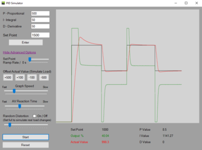
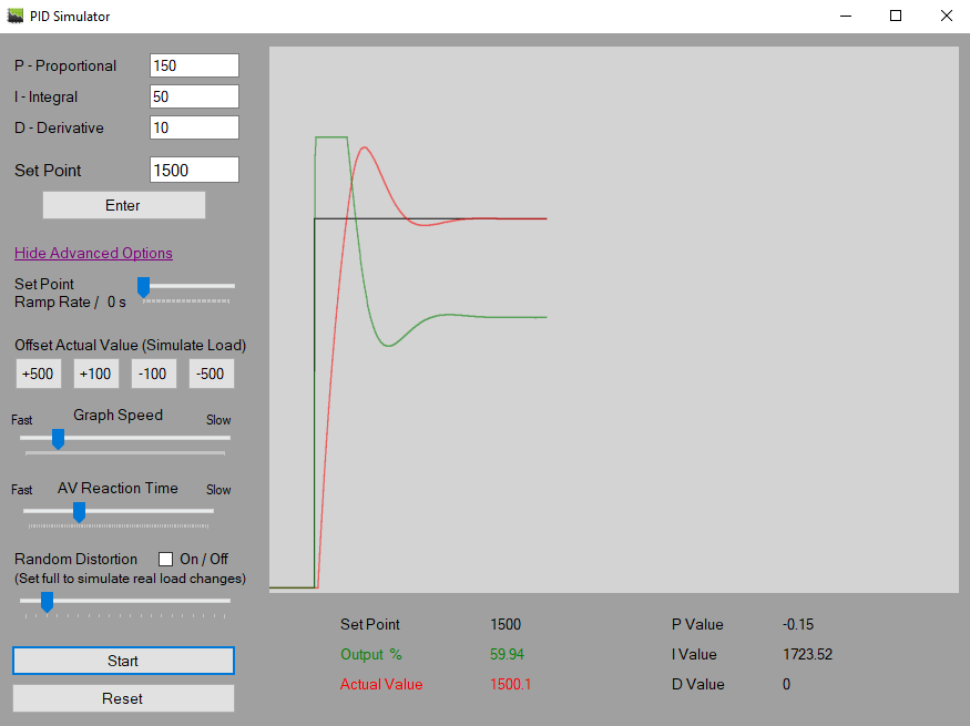
Once initial simulated values are selected, users can change the set point and run different simulation scenarios to observe how the simulated loop responds.
There is no single formula or step-by-step approach that applies to every PID control scenario. However, practicing with simulated examples can help users explore how different tuning adjustments affect loop behaviour. To experiment with PID tuning concepts in an interactive simulation environment, download the PID Simulator app from the Microsoft Store!
Observing the simulated loop response can help users identify which tuning values may be worth adjusting during the simulation exercise.
The PID controller is not reacting fast enough:
When reviewing the controller response, compare the initial output reaction with the response that follows. If the initial output response is strong but the process value continues to move slowly afterward, this may indicate that integral action needs to be reviewed.
If the initial output response is too slow, this may indicate that proportional action needs to be reviewed. Changes to proportional, integral, and derivative values should be made carefully while observing how each adjustment affects response speed, overshoot, and stability.
The PID controller is overshooting:
When reviewing the controller response, look at the initial output reaction and how far the process value moves past the set point. A large initial response may indicate that the proportional gain, and sometimes the integral gain, is contributing to the overshoot.
If the response speed is acceptable but overshoot is still present, derivative action may help reduce the overshoot and smooth the controller response. Any changes should be made carefully and reviewed against the applicable controller documentation, process requirements, and site procedures.
The PID controller is not stable, or oscillating:
An unstable or oscillating PID controller can be one of the more difficult issues to troubleshoot. Before changing PID values, first consider whether the issue may be caused by something outside the PID settings, such as mechanical problems, sensor behaviour, actuator limitations, process conditions, or other system factors.
If the output is rapidly switching between high and low values, the proportional gain may be too high. Reducing the proportional gain can help calm the response and improve stability.
If the output is not rapidly switching, but the process value continues to overcorrect above and below the set point, the integral gain may be too high. Reducing the integral gain can help reduce oscillation and allow the controller to settle.
If the loop remains difficult to control, it may be best to return to the basic tuning steps and review the effect of each PID value one at a time.
I hope this article helped explain the basic PID tuning concepts. Watch the video below for an interactive walkthrough.
Disclaimer
By accessing, downloading, installing, viewing, or using this application, website, videos, or related content, you acknowledge and agree to the full Disclaimer found at https://pidexplained.com/disclaimer/. This application, website, videos, and related content are provided for general informational and simulation practice purposes only. All settings, values, examples, outputs, demonstrations, and scenarios are simulated examples only, may not be accurate, complete, current, or error-free, and must not be copied, transferred, relied on, or applied to any actual controller, device, equipment, system, or process. This content is not OEM training, real-world tuning guidance, commissioning guidance, field instruction, or a substitute for qualified procedures, OEM documentation, training, or applicable requirements; use of this content does not qualify any person to tune, configure, adjust, or operate any real-world controller, device, equipment, system, or process, and any such work should only be performed by a properly qualified person.